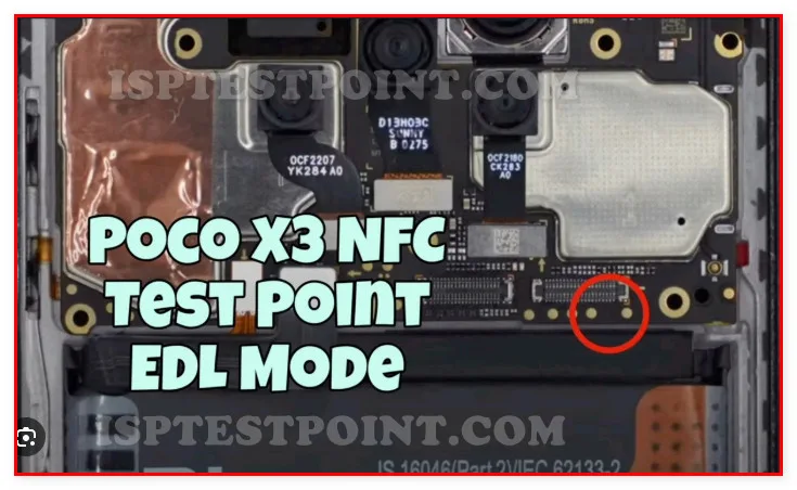
Poco X3 NFC Test Points Overview
The Poco X3 NFC is a mid-range device based on the Snapdragon 732G processor, featuring robust hardware diagnostics capabilities through strategically located test pads on the mainboard. Test points provide direct access to critical signal lines, power rails, and communication buses—essential for advanced troubleshooting when standard recovery modes fail. This reference guide enables technicians to perform secure hardware-level diagnostics, including FRP (Factory Reset Protection) bypass, firmware restoration, and dead-boot recovery procedures.

When to Use Test Points
Test points are required when conventional recovery methods are unavailable or ineffective. Common scenarios include:
- Dead-boot conditions (no display, no USB response)
- Corrupted bootloader or firmware preventing normal operation
- FRP lock requiring eMMC direct access
- Battery connectivity issues or charging problems
- Unresponsive to standard flashing tools or ADB commands
- EMI/hardware interference requiring signal-level verification
Direct hardware access bypasses software restrictions and enables full flash memory manipulation, making test points indispensable for professional repair workflows.
Access Procedure & Location
The Poco X3 NFC mainboard contains test pads located near the eMMC storage module and power management circuitry, typically on the rear side of the board. Technicians must remove the back cover and disconnect the battery before probing. Use a heat gun or targeted heat source to carefully lift the EMI shielding cage to expose test pad areas. Identify pads by visual reference to nearby component markings and the CPU footprint.
Critical test pads include ground reference points, power rails (VCCI, VCCQ), eMMC data lines (CMD, CLK, DAT0–DAT3), and reset signals. Maintain magnified vision and steady hand positioning when connecting test leads. Always probe GND first to establish reference potential before touching signal or power pads.
Safe Testing Practices
Observe strict safety protocols to prevent permanent hardware damage. All voltage levels on the Poco X3 NFC operate at 3.3V nominal; never apply external voltage exceeding this rating. Use regulated bench power supplies with current limiting (max 2A on VCC rails). Ensure proper grounding through a shielded test harness or calibrated multimeter probe.
Verify continuity before powering circuits. Wear anti-static wrist straps grounded to the chassis. Keep probes perpendicular to pad surfaces to avoid bridging adjacent traces. Power down immediately if abnormal readings (negative voltage, excessive current draw) occur.
Common Measurement Points
Essential readings for Poco X3 NFC diagnostics include: VCC rails (expect 3.3V ±5% when powered), GND continuity (0Ω resistance), eMMC CMD line pulse verification during boot sequence, and CLK signal presence. Monitor current draw on power rails—idle state should not exceed 100mA; active boot typically 500–800mA. Verify reset signal (RST) transitions from low to high during power-on sequence, indicating proper bootloader initialization.
Document all baseline measurements for comparison during subsequent repair attempts. Abnormal readings suggest component failure, trace damage, or IC-level malfunction requiring component-level rework or replacement.
Pin / Test Point Reference
| Pin | Description |
|---|---|
| GND | Ground reference point; always probe first to establish baseline — Multiple GND pads available near eMMC |
| VCC | 3.3V power rail for mainboard logic — Target: 3.3V ±5% under load |
| VCCQ | eMMC I/O voltage supply — Also 3.3V nominal |
| CMD | eMMC command line; data and status transfer — Pull-up to VCCQ via resistor network |
| CLK | eMMC clock signal; synchronizes data transfer — Verify presence during boot sequence |
| DAT0 | Primary eMMC data line — High-speed data transitions expected during read/write |
| RST | eMMC reset signal; active low — Monitor transition timing during power-on |
Tools required: Multimeter (DCV/continuity capability), Regulated bench power supply (3.3V, current-limited), MicroUSB test harness or ISP cable, UMT (Uni-Flash Tool) or Miracle Box for eMMC read/write, Heat gun or micro-soldering station for EMI shield removal, Anti-static wrist strap and grounding mat, Magnifying lamp (10×–20× magnification), Precision probe set or custom test lead harness
Supported operations: Read Full Firmware, Write eMMC (FRP Erase, Format), Dead Boot Repair, FRP Unlock, Bootloader Recovery, Power Rail Diagnostics, Signal Integrity Verification
⚠ Safety note: 3.3V nominal operation only. Never exceed supply voltage ratings. Improper probing risks eMMC corruption or trace damage. Use current limiting (max 2A). Ground yourself at all times. Disconnect battery before probing. If abnormal readings occur (negative voltage, >1A draw), power down immediately to prevent IC damage. Perform test point work only if experienced with component-level diagnostics.

Comments (0)
Be the first to comment.