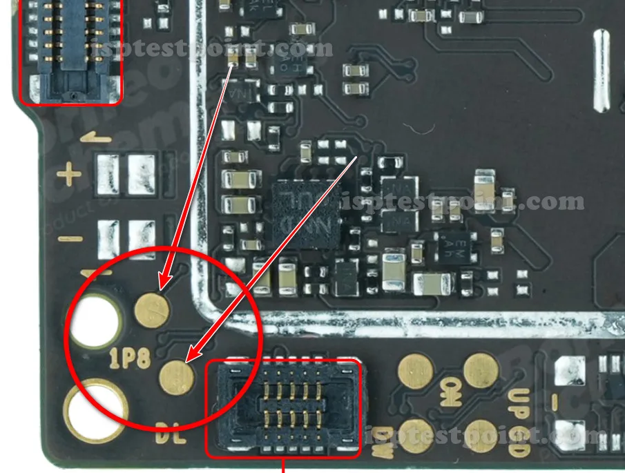
Test Point Overview
The Xiaomi Poco M3 features accessible test points and eMMC ISP pads that enable technicians to perform advanced diagnostics and repairs without requiring full UART or JTAG connectivity. These test points provide direct access to the device's storage interface, allowing for firmware extraction, FRP (Factory Reset Protection) bypass, and recovery of devices in dead-boot states. Understanding the correct identification and safe manipulation of these pads is essential for professional mobile repair work.

When to Use Test Points
Test points on the Poco M3 are primarily used in the following scenarios: performing FRP unlock when standard methods fail, flashing custom or stock firmware to resolve software corruption, recovering devices that fail to boot past the manufacturer logo, and reading device information for diagnostic purposes. These procedures require direct hardware access and should only be attempted by trained technicians familiar with micro-soldering and ISP protocols.
Access and Location Guide
The eMMC test pads on the Poco M3 are located on the mainboard near the storage IC. The specific pad layout follows standard eMMC ISP pinout conventions, with CLK, CMD, DAT0, VCC, GND, and VCCQ signals distributed across the component area. Precise location coordinates and pad identification require device-specific schematics or high-resolution board imagery. Technicians should inspect the board under magnification to identify the correct pads before attempting connection.
Testing Procedure
Before beginning: power off the device completely and disconnect the battery if possible. Establish a grounded work environment using an ESD wrist strap connected to a grounded mat. Use a multimeter to verify voltage readings at identified test points—GND should read 0V as reference, VCC typically 3.3V when powered. Connect ISP programming tools using fine-gauge wires or spring probes, ensuring secure contact without excessive pressure that could damage the pads. Follow the specific tool manufacturer's instructions for CLK, CMD, and DAT0 signal timing. Document all readings before and after testing.
Safety Precautions
Always wear an ESD wrist strap and use a grounded soldering mat when handling the mainboard. Avoid static discharge by maintaining constant contact with ground. Never apply voltage exceeding 3.6V to any test pad; excessive voltage can permanently damage the eMMC or surrounding components. Use low-power multimeter probes to minimize current draw during measurement. If the device is powered, ensure the USB cable is disconnected. Work in a dust-free environment and cover unused pads with protective tape. Improper test point connection can result in data loss or hardware failure—proceed only if you are confident in your technical skills.
Pin / Test Point Reference
| Pin | Description |
|---|---|
| CLK | eMMC clock signal for ISP communication — Typically 3.3V logic level |
| CMD | eMMC command line for ISP protocol — Bidirectional signal |
| DAT0 | eMMC data line (primary data path) — Part of 4-bit or 8-bit data bus |
| VCC | Main power supply for eMMC (3.3V nominal) — Required for ISP operation |
| GND | Ground reference for all signals — Multiple GND pads required |
| VCCQ | I/O voltage supply for eMMC (typically 3.3V or 1.8V) — Verify correct voltage before connection |
| RST | eMMC reset signal — May be optional for some ISP operations |
Tools required: UMT (Universal Multi-Tool), EasyJTAG Plus or equivalent eMMC reader, Multimeter (ESD-safe), Fine-gauge wire or spring probes, Micro-soldering equipment, ESD wrist strap and grounded mat, Magnification (10x–40x loupe or microscope)
Supported operations: FRP Erase, Firmware Read/Write, Dead Boot Repair, Pattern Lock Removal, Device Diagnostic Testing
⚠ Safety note: High risk of permanent hardware damage if incorrect voltage is applied. Never exceed 3.6V on any test pad. ESD protection mandatory—use grounded equipment only. Improper pad connection can destroy the eMMC and render the device unrecoverable. Proceed only with professional training and appropriate tools.

Comments (0)
Be the first to comment.