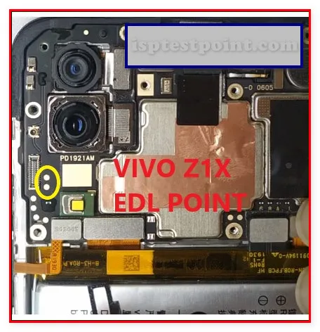
Vivo Z1X Test Point Overview — Essential Contact Points for Hardware Diagnostics and Repair Procedures
The Vivo Z1X test point system provides direct access to critical hardware signals required for advanced repair operations including FRP (Factory Reset Protection) removal, firmware flashing, and dead-boot recovery. Test points bypass software-level protections and enable technicians to communicate directly with the device's storage and boot circuitry. Proper identification and safe access to these contact pads are essential for successful diagnosis and component-level repair without risking permanent hardware damage.

When to Use Test Points — Identify Failure Scenarios Requiring Direct Hardware Access and Signal Verification
Test points become necessary when standard software-based recovery methods fail or are blocked by security locks. Common scenarios include: devices stuck in boot loops after failed updates, disabled charge circuits preventing power-on, FRP locks preventing factory reset completion, corrupted bootloader preventing OS load, and dead-boot conditions where the device shows no response to button input or charger connection. Test point access allows technicians to verify power rail integrity, signal continuity, and storage chip responsiveness without relying on functional firmware.
Locating Test Points on Board — Physical Positions and Component References for Safe Probe Connection
The Vivo Z1X motherboard contains multiple test pads typically located near the storage chip area and power management ICs. Test points are generally marked with small silk-screen labels or are identifiable as exposed metallic pads adjacent to major ICs. Reference the device schematic or board layout documentation to pinpoint exact coordinates. Key regions include the eMMC/storage vicinity, battery connector area, USB charging circuit, and CPU power delivery zones. Use magnification tools to safely identify target pads before probe contact. Avoid probing unmarked or damaged areas that may short adjacent traces.
Safe Testing Procedures — Proper Grounding, Voltage Measurement, and Component Protection During Diagnostics
Always establish a secure ground reference before measuring any signal. Connect the multimeter or test equipment ground to an exposed GND pad or device chassis ground point. Verify multimeter settings match expected signal voltage ranges before contact. Use fine-tip probes to avoid bridging adjacent pads. Perform all measurements with the device powered off unless the procedure specifically requires live testing. Remove the battery before extended probing sessions to prevent accidental short circuits. Apply gentle, perpendicular pressure to test pads—excessive force damages fragile connections and trace layers.
Common Test Point Applications — Battery, Charging, Display, and Boot Signal Verification Workflows
Battery voltage test points confirm power delivery chain integrity—measure 3.7V nominal on primary battery rails. Charging circuit test points verify USB data and power line continuity, critical for FRP bypass and firmware upload procedures. Storage chip test points (CLK, CMD, DAT lines) validate eMMC communication integrity during read/write operations. Boot signal verification uses dedicated test pads to confirm CPU initialization sequences. Display backlight test points isolate LCD power issues from software problems. Each application requires specific probe placement, voltage expectations, and safety precautions—consult device-specific technical documentation before beginning diagnostics.
Pin / Test Point Reference
| Pin | Description |
|---|---|
| GND | Ground reference pad — Primary grounding point for all measurements |
| VCC | Main power supply rail — Typically 3.7V battery nominal |
| CLK | eMMC clock signal — Storage communication line |
| CMD | eMMC command line — Storage command interface |
| DAT0 | eMMC data line 0 — Primary storage data bus |
Tools required: Digital multimeter, Fine-tip probe set, Magnification tool (loupe/microscope), UMT (Universal Multi-Tool), EasyJTAG Plus, ISP flash programmer, Anti-static wrist strap
Supported operations: FRP Erase, Firmware Read, Dead Boot Repair, Power Rail Verification, Storage Chip Communication Test, Boot Signal Verification
⚠ Safety note: High-voltage components present—verify all measurements before probe contact. Do not probe live circuits without proper equipment grounding. Risk of permanent IC damage if incorrect pads are shorted. Battery must be disconnected during extended test point access.

Comments (0)
Be the first to comment.