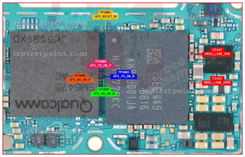
What Is ISP Pinout
ISP (In-System Programming) is a direct hardware method that allows technicians to communicate with the NAND flash memory on a device's PCB without using the standard USB or EDL software interface. For the Samsung SM-A366, ISP is used when conventional software-based methods — such as ADB, Download Mode, or Emergency Download (EDL) — are unavailable due to a corrupted bootloader, damaged USB port, or a locked FRP state that blocks normal entry points. By soldering or probing the designated test pads on the motherboard, a compatible ISP tool can read, write, or erase the eMMC storage directly at the hardware level, bypassing all software locks.

SM-A366 ISP Pinout Diagram
The ISP interface on the SM-A366 follows the standard eMMC pinout convention. The key signals required for direct NAND communication are listed below. Exact pad coordinates on the PCB should be verified using a high-resolution board schematic or a trusted board-view file, as pad positions can vary between PCB revisions.
- CLK – Clock signal; synchronizes data transfer between the tool and eMMC.
- CMD – Command line; sends read/write instructions to the flash chip.
- DAT0 – Primary data line; mandatory for all ISP operations.
- DAT1 – Secondary data line for 4-bit bus width transfers.
- DAT2 – Third data line; part of 4-bit bus configuration.
- DAT3 – Fourth data line; completes the 4-bit bus and is required for reliable reads.
- VCC – Main power supply to the eMMC (typically 2.9 V–3.3 V).
- VCCQ – I/O supply voltage for signal lines (typically 1.8 V).
- GND – Ground reference; must share common ground with the ISP tool.
When Technicians Use ISP
ISP becomes necessary in several critical repair scenarios. A dead-boot condition — where the device shows no signs of life and does not respond to USB — is the most common. FRP (Factory Reset Protection) bypass is another frequent use case when the Google account lock cannot be cleared through software. ISP is also used when the device cannot enter EDL (Emergency Download) mode due to a damaged test point, broken USB controller, or locked security fuse. In all these cases, direct NAND access via ISP is the only remaining path to recover or service the device.
Accessing the Test Points
Follow this procedure when connecting to the SM-A366 ISP interface:
- Power off the device completely and disconnect the battery before any soldering.
- Disassemble the device and expose the main PCB using appropriate opening tools.
- Locate the eMMC ISP test pads using a board-view file or a verified pinout diagram.
- Clean pad surfaces gently with isopropyl alcohol (99%) and allow to dry.
- Solder thin magnet wire (28–32 AWG) or use a fine-tip ISP probe clip to each test pad.
- Connect wires to the corresponding pins on your ISP adapter or socket.
- Open your ISP software, select the correct eMMC chip profile, and initiate the read or erase operation.
- After the operation completes, carefully remove connections and reassemble the device.
Safety Tips and Precautions
Working at the ISP level carries significant risk of permanent board damage if precautions are ignored. Always observe the following guidelines:
- Confirm supply voltages before powering: VCC must not exceed 3.3 V and VCCQ must not exceed 1.8 V for most eMMC configurations.
- Never apply power through the ISP tool while the battery is still connected to the board.
- Avoid bridging adjacent pads — a short between CLK and CMD can corrupt the eMMC controller.
- Use flux sparingly; excess flux residue can cause leakage currents between signal lines.
- Always verify ground continuity with a multimeter before initiating any ISP session.
- Work under magnification and use ESD-safe tools to prevent static discharge damage to sensitive components.
Pin / Test Point Reference
| Pin | Description |
|---|---|
| CLK | Clock signal for eMMC communication — Exact pad location unconfirmed; verify with board-view |
| CMD | Command line for read/write instructions — Exact pad location unconfirmed; verify with board-view |
| DAT0 | Primary data line; required for all ISP operations — Exact pad location unconfirmed |
| DAT1 | Data line 1 for 4-bit bus transfers — Exact pad location unconfirmed |
| DAT2 | Data line 2 for 4-bit bus transfers — Exact pad location unconfirmed |
| DAT3 | Data line 3; completes 4-bit eMMC bus — Exact pad location unconfirmed |
| VCC | Main eMMC power supply (2.9 V–3.3 V typical) — Confirm voltage before applying |
| VCCQ | I/O voltage for signal lines (1.8 V typical) — Confirm voltage before applying |
| GND | Ground reference; common with ISP tool ground — Verify continuity before starting session |
Tools required: EasyJTAG Plus, UMT ISP Adapter, Medusa Pro II, Riff Box 2, MOORC E-Mate Pro (eMMC socket adapter), Fine-tip soldering iron, 28–32 AWG magnet wire, Digital multimeter
Supported operations: Read Firmware, Write Firmware, FRP Erase, Dead Boot Repair, eMMC Full Backup, Bootloader Repair
⚠ Safety note: Do not exceed 3.3 V on VCC or 1.8 V on VCCQ. Disconnect battery before connecting ISP tool. Bridging signal pads may permanently damage the eMMC. Use ESD protection at all times.

Comments (0)
Be the first to comment.