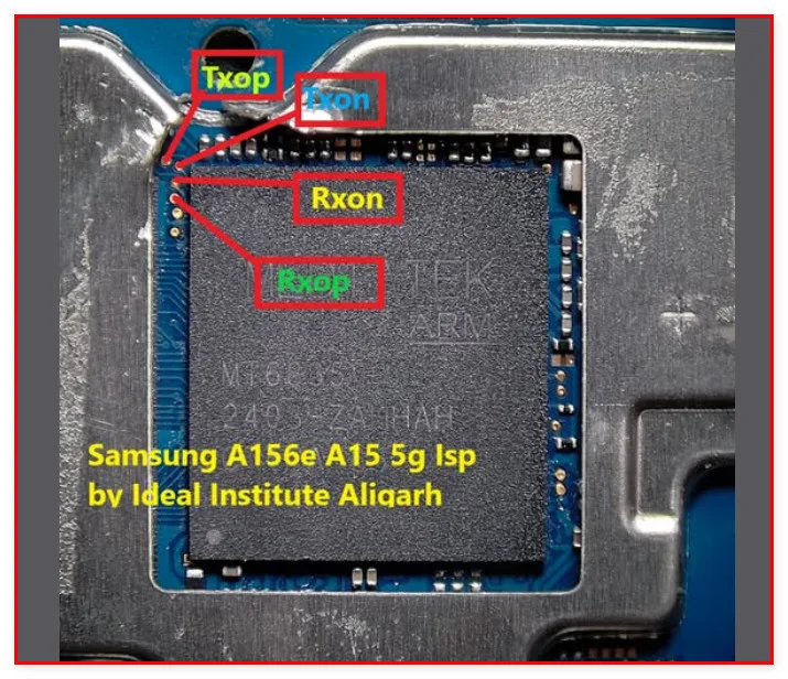
What Is ISP Pinout
ISP (In-System Programming) pinout is a hardware-level data access method that allows technicians to communicate directly with a device's NAND flash (eMMC or UFS) storage by connecting to specific testpoints on the PCB, bypassing the CPU entirely. Rather than relying on software boot sequences or USB communication, ISP establishes a direct electrical link to the flash chip's bus lines — CLK, CMD, DAT0, VCC, VCCQ, and GND — enabling raw read and write operations. This approach is critical for data recovery, firmware flashing, and security partition manipulation when conventional methods fail. On the Samsung SM-A15 5G (S156VL), ISP access targets the eMMC interface lines routed to exposed testpads on the motherboard.

When Technicians Use ISP
ISP is typically a last-resort or advanced-repair technique applied in the following scenarios:
- Dead boot / hard brick: The device fails to power on or is stuck in a boot loop after a failed OTA update or interrupted flash attempt.
- FRP (Factory Reset Protection) lock: The Google account lock cannot be bypassed through software tools or ADB due to a locked bootloader or disabled USB debugging.
- Pattern or PIN lock: Screen lock credentials are forgotten and no trusted recovery method is accessible.
- Failed UFI Box or JTAG attempts: When standard JTAG pinouts are not recognized or the device is not detected by the box tool via normal interface.
- Firmware corruption: Partition table damage or bootloader corruption requiring direct eMMC write access to restore a valid firmware image.
SM-A15 5G ISP Pin Locations
The Samsung SM-A15 5G (S156VL) uses a MediaTek Dimensity 6100+ platform. The eMMC testpoints are located on the rear face of the main PCB, typically near the eMMC flash chip. The standard ISP interface lines to locate and connect are CLK, CMD, DAT0, VCC (2.9V), VCCQ (1.8V), and GND. Exact pad coordinates for the S156VL variant have not been independently verified in publicly available schematics at time of writing; technicians should cross-reference with a verified UFI or Easy-JTAG pinout diagram specific to this board revision before proceeding.
Step-by-Step Access Procedure
Follow these steps to perform an ISP connection on the SM-A15 5G:
- Disassemble the device and remove the motherboard following standard Samsung mid-range disassembly procedures.
- Clean the PCB surface around the eMMC area with isopropyl alcohol (99%) to expose testpad surfaces.
- Identify and solder or clip onto CLK, CMD, DAT0, GND, VCC, and VCCQ testpoints using fine-gauge wire or an ISP clip jig if available.
- Connect the wired leads to your ISP-capable box tool (e.g., Easy-JTAG Plus, UFI Box, or UMT).
- Launch the appropriate software, select MediaTek eMMC ISP mode, and power the board via the tool's regulated supply.
- Execute the desired operation: firmware read/write, FRP erase, or full backup.
Safety Tips and Precautions
Working at the ISP level carries significant risk. Observe the following precautions:
- Voltage regulation: eMMC VCC requires ~2.9V and VCCQ ~1.8V. Incorrect voltage will permanently damage the flash chip.
- ESD protection: Always work on an anti-static mat and wear a grounded wrist strap. Static discharge can corrupt or destroy the eMMC.
- Full backup first: Before any write or erase operation, perform a complete eMMC dump and store it safely.
- No USB power during ISP: Do not connect the battery or USB simultaneously unless your tool explicitly supports it.
- Verify pinout: Never assume testpad locations — confirm against a board-specific schematic or trusted community diagram before soldering.
Pin / Test Point Reference
| Pin | Description |
|---|---|
| CLK | eMMC clock signal line — Testpad location unverified for S156VL — confirm via schematic |
| CMD | eMMC command line — Testpad location unverified for S156VL — confirm via schematic |
| DAT0 | eMMC data line 0 — Testpad location unverified for S156VL — confirm via schematic |
| VCC | eMMC core power supply (~2.9V) |
| VCCQ | eMMC I/O power supply (~1.8V) |
| GND | Ground reference — multiple available points on PCB |
Tools required: Easy-JTAG Plus, UFI Box, UMT (Ultimate Multi Tool), Fine-gauge ISP wire or ISP clip jig, Anti-static mat and wrist strap, Isopropyl alcohol 99% and cleaning brush
Supported operations: Read Firmware / Full eMMC Dump, FRP Erase, Dead Boot Repair, Pattern / PIN Lock Remove, Firmware Write / Flash
⚠ Safety note: Incorrect voltage (VCC/VCCQ) will permanently destroy the eMMC. Always back up before writing. Use ESD protection. Do not apply battery/USB power simultaneously with ISP tool power.

Comments (0)
Be the first to comment.