What Is ISP Pinout
ISP (In-System Programming) pinout is a hardware-level access method that allows technicians to communicate directly with the NAND flash memory chip on the Samsung SM-A145M motherboard. Instead of relying on the device's operating system or USB interface, ISP bypasses the CPU boot sequence entirely and establishes a direct connection to the eMMC storage using dedicated test pads on the PCB. This technique is essential when conventional software tools and download mode cannot reach the flash memory. For the SM-A145M, which runs on a MediaTek Helio G80 platform, ISP provides raw read and write access to all partitions — including userdata, FRP, and bootloader regions — making it a cornerstone method in advanced mobile repair workflows.

When to Use ISP
ISP is the appropriate approach in several critical repair scenarios. The most common is a dead boot condition, where the device shows no signs of life and cannot enter download or recovery mode. ISP is also necessary when the USB port is physically damaged or the USB controller has failed, preventing any PC-based flashing through normal means. Technicians also turn to ISP for FRP (Factory Reset Protection) removal when the Google account credentials are unavailable and software-based FRP tools are ineffective. Additionally, a corrupted bootloader or a failed OTA update that renders the SM-A145M unresponsive can be resolved through direct NAND access via ISP. Locked bootloaders that block standard flashing are another valid use case.
SM-A145M ISP Test Points
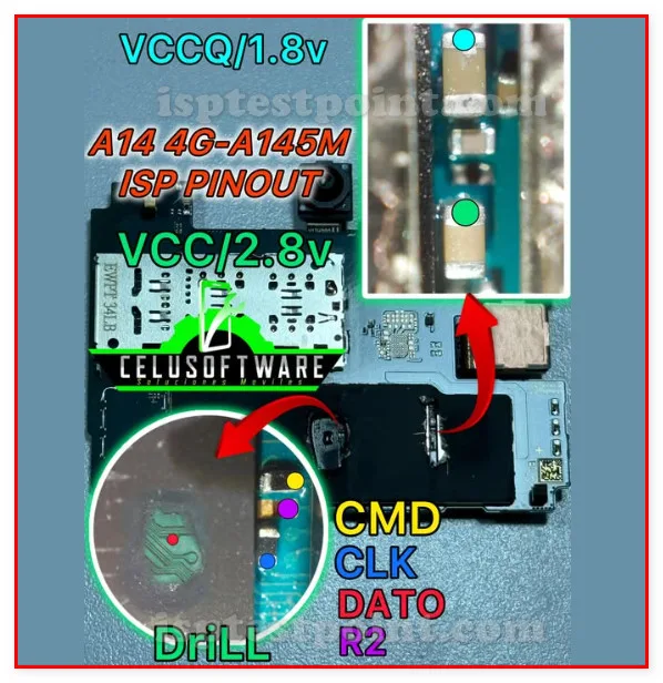
The ISP test points on the SM-A145M motherboard correspond to the standard eMMC bus signals. These pads are located on the back side of the main PCB, near the eMMC flash chip. The key signals required for ISP are listed below. Note that exact pad silk-screen labels and precise physical coordinates should be verified against a board-level schematic or a confirmed ISP pinout diagram specific to the A145M revision, as pad positions can vary between PCB revisions.
- CLK – eMMC clock signal pad
- CMD – Command line pad
- DAT0 – Data line 0 pad (minimum required for ISP)
- VCC – eMMC core power supply (typically 3.3V)
- VCCQ – eMMC I/O power supply (typically 1.8V)
- GND – Ground reference pad
Exact resistor or capacitor pad references for CLK, CMD, and DAT0 on the SM-A145M PCB are not confirmed in publicly available documentation and should be sourced from a verified board diagram before proceeding.
Connecting the ISP Programmer
Begin by fully disassembling the SM-A145M and removing the motherboard. Clean the ISP test pad area with isopropyl alcohol. Power off the board completely and do not connect the battery during wiring. Using fine 30 AWG wire, solder leads to CLK, CMD, DAT0, GND, VCC, and VCCQ pads. Connect each wire to the corresponding ISP socket pins on your programmer. Open your ISP tool software, select the MediaTek eMMC platform, and choose the SM-A145M or equivalent profile. Apply power through the programmer only — do not attach the battery. Initiate detection and confirm the eMMC chip ID is recognized before proceeding with any read or write operation.
Safety Tips and Precautions
Always use an ESD wrist strap and anti-static mat when handling the motherboard. Verify voltage levels with a multimeter before connection — applying 3.3V to a 1.8V VCCQ line will permanently damage the eMMC. Use a regulated power supply or rely on the programmer's built-in voltage rails. Avoid bridging adjacent pads during soldering, particularly around the eMMC clock line, as shorts can destroy the flash chip instantly. Never attempt ISP on a device with a swollen or connected battery. Back up the full eMMC image before making any write operations. Double-check programmer cable polarity before powering on.
Pin / Test Point Reference
| Pin | Description |
|---|---|
| CLK | eMMC clock signal test pad — Exact pad location unconfirmed; verify with board schematic |
| CMD | eMMC command line test pad — Exact pad location unconfirmed; verify with board schematic |
| DAT0 | eMMC data line 0 — minimum required for ISP communication — Exact pad location unconfirmed; verify with board schematic |
| VCC | eMMC core power supply, typically 3.3V |
| VCCQ | eMMC I/O power supply, typically 1.8V — Confirm voltage before connection to avoid eMMC damage |
| GND | Ground reference pad |
Tools required: EasyJTAG Plus, UMT Pro (UFI Box), Medusa Pro II, RIFF Box 2, 30 AWG enameled wire, Fine-tip soldering iron, Isopropyl alcohol (99%), ESD wrist strap and mat
Supported operations: Read Firmware (eMMC Dump), Write Firmware (Full Restore), FRP Erase, Dead Boot Repair, Bootloader Repair, IMEI Repair (where legally permitted)
⚠ Safety note: Verify VCC (3.3V) and VCCQ (1.8V) before connection. Wrong voltage will permanently destroy the eMMC. Disconnect battery before ISP wiring. Use ESD protection at all times.

Comments (0)
Be the first to comment.