What Is ISP Pinout
ISP — In-System Programming — is a direct hardware communication method that allows technicians to interface with a device's NAND flash memory (eMMC) without relying on the main CPU or operating system. On the Samsung SM-A145 (Galaxy A14 4G), this technique is critical when standard software routes such as ADB, Download Mode, or USB-based flashing are completely inaccessible. By connecting a compatible programmer tool directly to the eMMC test pads on the motherboard, a technician can read, write, or erase the flash chip at the hardware level. This bypasses software locks, corrupted bootloaders, and broken firmware states — making ISP one of the most powerful tools in mobile hardware repair.

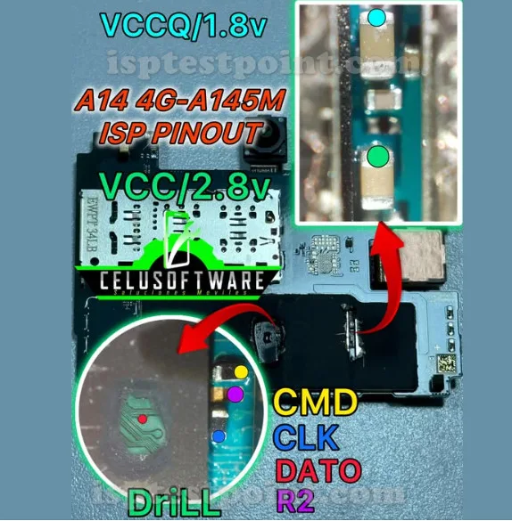
SM-A145 ISP Pinout Diagram
The Samsung SM-A145 is powered by the MediaTek Helio G80 (MT6769V/CU) SoC and uses an eMMC 5.1 flash storage interface. The ISP test points are located on the rear side of the motherboard, typically clustered near the eMMC chip. The standard eMMC ISP pin assignments for this device are as follows:
- CLK — eMMC clock signal test pad
- CMD — Command line test pad
- DAT0 — Data line 0 test pad (primary data path for ISP mode)
- VCC — eMMC core power supply (typically 3.3V)
- VCCQ — eMMC I/O power supply (typically 1.8V)
- GND — Ground reference pad
Exact pad coordinates and physical labeling on the PCB are not standardized across board revisions. Technicians should verify pad locations using a high-resolution board schematic or a trusted ISP pad map specific to the SM-A145 board revision before soldering.
When Technicians Use ISP
ISP access on the SM-A145 is typically required in the following scenarios:
- Dead boot / hard brick: Device shows no signs of life and cannot enter Download Mode.
- Bootloop: Device restarts repeatedly due to corrupted firmware or a failed OTA update.
- FRP lock: Factory Reset Protection is active and cannot be cleared through software methods.
- Inaccessible storage: File system corruption prevents normal data access or flashing.
- IMEI restoration: After motherboard swap or eMMC-level corruption of the modem partition.
Step-by-Step Access Procedure
Follow these steps to safely connect a programmer via ISP on the SM-A145:
- Fully disassemble the device and remove the motherboard following standard anti-static procedure.
- Identify and clean the ISP test pads using isopropyl alcohol (99%) and a fine brush.
- Solder thin gauge wire (36–38 AWG) to CLK, CMD, DAT0, VCC, VCCQ, and GND pads — or use a dedicated ISP clip/jig if available for this model.
- Connect wires to the corresponding ISP socket on your programmer (UMT, EasyJTAG Plus, or Medusa Pro).
- Launch the programmer software, select MediaTek eMMC / SM-A145 or compatible profile, and power the device through the programmer's regulated supply.
- Execute the desired operation: read firmware, erase FRP, or write stock image.
Safety Tips and Precautions
Working at the ISP level carries real risk of permanent damage if precautions are ignored:
- Voltage regulation: VCC must be 3.3V and VCCQ must be 1.8V. Applying incorrect voltages will permanently damage the eMMC chip.
- ESD protection: Always work on an anti-static mat and wear a grounded wrist strap. Static discharge can destroy both the eMMC and the SoC.
- Do not hot-swap: Never connect or disconnect ISP wires while power is applied.
- Verify pad identity: Confirm each pad with a multimeter before applying solder. Bridging adjacent pads can short critical power rails.
- Backup first: Always perform a full eMMC read/backup before writing or erasing any partition.
Pin / Test Point Reference
| Pin | Description |
|---|---|
| CLK | eMMC clock signal test pad — Exact pad location varies by PCB revision; verify with schematic |
| CMD | eMMC command line test pad — Exact pad location varies by PCB revision; verify with schematic |
| DAT0 | eMMC data line 0 — primary data path used in ISP 1-bit mode — Exact pad location varies by PCB revision |
| VCC | eMMC core power supply — 3.3V — Confirm voltage before connecting; incorrect voltage destroys eMMC |
| VCCQ | eMMC I/O power supply — 1.8V — Must be 1.8V for Helio G80 platform |
| GND | Ground reference — multiple ground pads available on PCB — Use nearest verified ground pad to minimize noise |
Tools required: UMT (Ultimate Multi Tool), EasyJTAG Plus, Medusa Pro II, RIFF Box 2, 36–38 AWG magnet wire, Anti-static mat and wrist strap, Precision soldering iron (≤300°C tip), Isopropyl alcohol 99%, Digital multimeter
Supported operations: Read Firmware (eMMC Full Dump), Write Firmware (Stock ROM Restore), FRP Erase, Dead Boot Repair, Bootloop Repair, IMEI Restoration (modem partition write), Partition Backup and Restore
⚠ Safety note: VCC must be 3.3V; VCCQ must be 1.8V. Wrong voltage permanently destroys the eMMC. Always ESD-protect. Never hot-swap ISP connections. Backup full eMMC before any write or erase operation.

Comments (0)
Be the first to comment.