What Is ISP Pinout
ISP (In-System Programming) is a hardware-level method that allows technicians to communicate directly with a device's NAND flash storage by bypassing the main CPU and operating system entirely. Instead of relying on ADB, Download Mode, or USB protocols, ISP establishes a direct electrical connection to the eMMC or UFS memory chip's dedicated bus lines on the PCB. This makes it possible to read, write, or erase flash memory even when the device cannot power on, boot, or respond to standard software tools. For Samsung devices like the SM-A145P, ISP is an essential last-resort technique when conventional methods have failed.

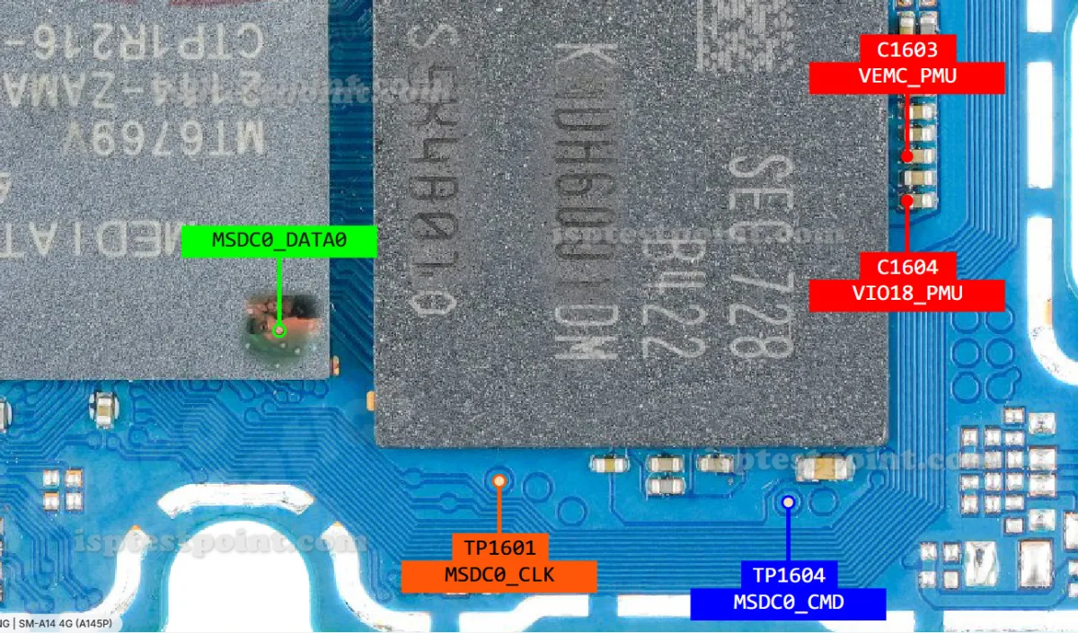
SM-A145P ISP Test Points
The Samsung SM-A145P uses a MediaTek Helio G80 chipset paired with eMMC 5.1 flash storage. The ISP test points are small exposed copper pads located on the main PCB, typically near or beneath the eMMC chip. Technicians must make precise contact with these pads to establish the eMMC bus connection. The standard eMMC ISP lines required are listed below:
- CLK – Clock signal line; synchronises data transfer between programmer and eMMC.
- CMD – Command line; carries read/write instructions to the eMMC controller.
- DAT0 – Primary data line; transfers payload data during ISP operations.
- VCC – Main power supply to the eMMC (typically 3.3 V).
- VCCQ – I/O voltage rail for eMMC logic interface (typically 1.8 V).
- GND – Ground reference; must be stable for reliable communication.
Exact pad coordinates and silkscreen labels on the SM-A145P PCB should be verified against a current board-view file or a trusted schematic before proceeding, as pad positions can vary between PCB revisions.
When Technicians Use ISP
ISP is called upon in several critical repair scenarios. A dead boot situation — where the device shows no sign of life and Download Mode is inaccessible — requires direct flash access to restore a valid bootloader or firmware. FRP (Factory Reset Protection) removal at the hardware level is performed via ISP when the Google account lock cannot be bypassed through software. Pattern, PIN, or password lock removal, IMEI repair, and corrupted firmware recovery are additional use cases where ISP provides the only viable path forward.
How to Access the Pinout
Follow these steps carefully when connecting via ISP test points on the SM-A145P:
- Fully disassemble the device and remove the PCB from the chassis.
- Disconnect the battery to prevent accidental short circuits during preparation.
- Identify the eMMC ISP test pads using a verified board-view or schematic.
- Clean the pads gently with isopropyl alcohol and a soft brush.
- Solder fine gauge (0.1 mm) ISP wires or use a dedicated ISP clip/adapter to each pad.
- Connect the wires to the corresponding ports on your ISP programmer (EasyJTAG Plus, UFi Box, or similar).
- Launch the appropriate software, select the MediaTek eMMC profile, and run your desired operation.
Safety Tips and Warnings
ISP work carries significant risk of permanent board damage if performed incorrectly. Always observe the following precautions:
- Confirm supply voltages before powering on — applying 3.3 V to a 1.8 V VCCQ line will destroy the eMMC.
- Never work on a board with the battery connected unless the tool explicitly requires it.
- Use a quality temperature-controlled soldering iron; excess heat lifts pads irreversibly.
- Double-check all wire connections for shorts before applying power.
- Back up the original firmware dump before performing any write or erase operation.
Pin / Test Point Reference
| Pin | Description |
|---|---|
| CLK | eMMC clock line — synchronises all data transfers during ISP session — Exact pad location — verify with board-view before soldering |
| CMD | eMMC command line — carries read/write/erase instructions to flash controller — Exact pad location — verify with board-view before soldering |
| DAT0 | Primary eMMC data line — transfers firmware payload bytes — Exact pad location — verify with board-view before soldering |
| VCC | eMMC core power supply — typically 3.3 V on this platform — Confirm voltage with multimeter before connecting programmer |
| VCCQ | eMMC I/O voltage rail — typically 1.8 V logic level — Do NOT apply 3.3 V to this line; eMMC will be damaged |
| GND | Ground reference — connect to any confirmed ground point on PCB — A stable ground is critical for reliable ISP communication |
Tools required: EasyJTAG Plus, UFi Box, UMT Pro, Medusa Pro II, ISP soldering jig or 0.1 mm ISP wire, Temperature-controlled soldering iron, Isopropyl alcohol (99%), SM-A145P board-view / schematic
Supported operations: Dead Boot Repair, FRP Erase, Firmware Read / Backup, Firmware Write / Restore, Pattern / PIN / Password Unlock, IMEI Repair (via EFS partition write), Corrupted Bootloader Recovery
⚠ Safety note: Verify VCC (3.3 V) and VCCQ (1.8 V) before powering on. Incorrect voltage kills eMMC instantly. Always disconnect battery before wiring ISP pads. Back up flash before any write operation.

Comments (0)
Be the first to comment.