What Is ISP Pinout
ISP (In-System Programming) is a hardware-level method that allows technicians to communicate directly with the eMMC NAND flash storage on the Samsung SM-A135 (Galaxy A13) without relying on the device's operating system, bootloader, or USB port. By attaching programmer cables directly to specific test pads on the PCB, the programmer reads and writes raw data to the flash chip. This bypasses software locks, corrupted bootloaders, and failed USB interfaces entirely. For the SM-A135, which runs on the MediaTek Helio G80 platform, ISP is the most reliable low-level access method when standard flashing routes are unavailable.

When to Use ISP
ISP is the preferred recovery method in scenarios where conventional tools fail. Use ISP on the SM-A135 when:
- The device is stuck in a hard brick or dead-boot state and does not respond to USB.
- EDL (Emergency Download Mode) is inaccessible due to MediaTek authentication requirements or a damaged USB port.
- Fastboot mode is unavailable or the bootloader partition is corrupted.
- FRP (Factory Reset Protection) cannot be removed via software tools due to a locked or damaged userdata partition.
- The USB charging IC or port is physically damaged, making cable-based flashing impossible.
ISP provides a direct electrical path to the eMMC, making it the last-resort but highly effective recovery option.
SM-A135 ISP Test Points
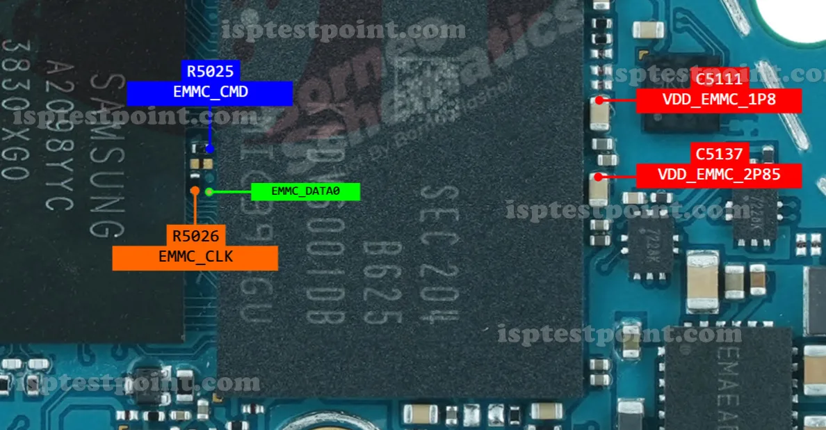
The ISP test points on the SM-A135 PCB are located near the eMMC flash chip on the main board. The standard eMMC ISP interface uses the following signal lines:
- CLK – Clock signal, synchronizes data transfer between programmer and eMMC.
- CMD – Command line, sends read/write instructions to the eMMC.
- DAT0 – Primary data line for eMMC communication.
- VCC – Main power supply to the eMMC (typically 3.3V).
- VCCQ – I/O voltage supply (typically 1.8V).
- GND – Ground reference.
Exact pad coordinates and silkscreen labels for the SM-A135 vary by PCB revision. Technicians should use a high-resolution board schematic or a verified ISP pinout diagram specific to the A135 revision before probing.
How to Connect ISP Cables
Follow these steps carefully when connecting ISP programmer cables to the SM-A135:
- Power down the device completely and disconnect the battery before beginning.
- Disassemble the handset and expose the main PCB. Locate the eMMC test pads using a reference diagram.
- Clean the test pad area with isopropyl alcohol (99%) and allow it to dry.
- Solder fine gauge wire or use a spring-pin ISP adapter to each test point: CLK, CMD, DAT0, VCC, VCCQ, and GND.
- Connect the wires to the corresponding terminals on your programmer (e.g., EasyJTAG Plus or UMT ISP adapter).
- Launch the programmer software, select the SM-A135 or MediaTek eMMC profile, and power the board through the programmer's VCC output.
- Initiate the desired operation (read, write, or FRP erase) and do not disturb connections during the process.
Safety Tips and Warnings
ISP work on the SM-A135 carries real hardware risks. Observe these precautions:
- Always wear an ESD wrist strap. Static discharge can permanently destroy the eMMC or CPU.
- Never apply more than 3.3V to VCC or 1.8V to VCCQ. Overvoltage will kill the flash chip instantly.
- Double-check polarity before powering up. Reversed GND and VCC connections cause irreversible damage.
- Do not attempt ISP on a wet or corroded board without cleaning it first.
- Avoid excessive heat when soldering to test pads — use a fine-tip iron at a controlled temperature.
- Always back up a full eMMC read before performing any write or erase operation.
Pin / Test Point Reference
| Pin | Description |
|---|---|
| CLK | eMMC clock signal — synchronizes all data transfers between programmer and NAND — Exact pad location unconfirmed; verify against A135 board schematic |
| CMD | eMMC command line — carries read/write/erase command packets — Exact pad location unconfirmed; verify against A135 board schematic |
| DAT0 | Primary eMMC data line — carries firmware data during read/write operations |
| VCC | eMMC main power supply — typically 3.3V; supplied by programmer or onboard regulator |
| VCCQ | eMMC I/O voltage — typically 1.8V; must not exceed spec |
| GND | Ground reference — common ground shared between programmer and PCB |
Tools required: EasyJTAG Plus with ISP adapter, UMT (Ultimate Multi Tool) ISP box, Medusa Pro II, Fine-tip soldering iron, 30–32 AWG insulated wire, Isopropyl alcohol 99%, ESD wrist strap, Digital multimeter, High-resolution A135 PCB schematic
Supported operations: Read Firmware (Full eMMC Dump), Write Firmware, FRP Erase, Dead Boot Repair, Bootloader Repair, IMEI Backup
⚠ Safety note: Use 3.3V VCC and 1.8V VCCQ only. Always wear ESD protection. Verify pinout with a schematic before powering. Incorrect voltage or reversed polarity will permanently destroy the eMMC.

Comments (0)
Be the first to comment.