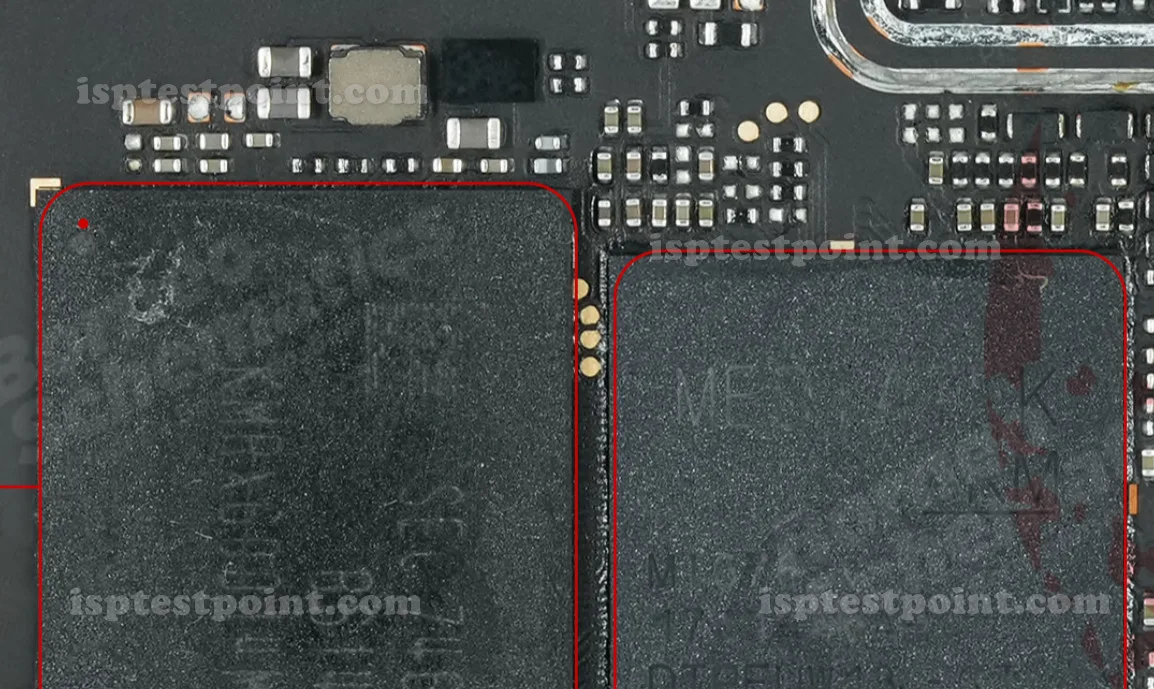
OPPO F5 CPH1723 Test Point Overview
The OPPO F5 (model CPH1723) is a MediaTek Helio P23 (MT6763T)-powered smartphone released in 2017. When the device suffers a hard brick, bootloop, failed OTA, or is locked with FRP (Factory Reset Protection) that cannot be cleared through normal recovery, technicians use the ISP (In-System Programming) eMMC test points on the motherboard to communicate directly with the eMMC flash chip, bypassing the CPU boot sequence entirely.

When to Use the Test Points
- Dead Boot / Hard Brick: Device shows no signs of life after a failed flash or interrupted update.
- FRP / Google Account Lock: Standard ADB or recovery methods are unavailable or blocked.
- Pattern / PIN Lock: Security screen cannot be bypassed via software tools.
- Firmware Read/Backup: Creating a full eMMC dump before performing risky repairs.
- IMEI Restoration: After a corrupt NVRAM partition caused by a bad flash.
ISP eMMC Test Point Locations
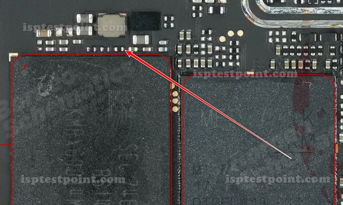
To access the ISP pads on the OPPO F5 CPH1723, fully disassemble the device and remove the motherboard. The eMMC ISP test pads are located on the back (component) side of the motherboard, near the eMMC chip package. Clean the pads carefully with isopropyl alcohol before attaching wires or a pogo-pin jig.
The standard eMMC ISP pin signals to identify and connect are: CLK, CMD, DAT0, VCC (2.9V), VCCQ (1.8V), and GND. RST is not always required but may be needed depending on the tool used. Use 28–30 AWG enamelled wire or a dedicated ISP jig clip for reliable contact.
Step-by-Step Procedure Overview
- Power off the device and remove the battery.
- Disassemble fully and remove the PCB from the frame.
- Locate and identify the eMMC ISP test pads (see pin table below).
- Solder or clip thin wires to CLK, CMD, DAT0, VCC, VCCQ, and GND pads.
- Connect wires to your ISP-capable box (EasyJTAG Plus, UFI Box, or Medusa Pro II).
- Launch the box software, select eMMC ISP mode, and power on via the tool.
- Read the eMMC, perform the required operation (FRP erase, firmware write, etc.), then disconnect and reassemble.
Safety Notes
Always verify supply voltages before powering on: VCC must be 2.9V–3.0V and VCCQ must be 1.8V. Incorrect voltages will permanently destroy the eMMC chip. Do not apply power to the battery connector while ISP wires are attached. Use a current-limited bench power supply if your tool does not regulate voltage internally. Static discharge can damage the board — use an anti-static wrist strap throughout the procedure.
Pin / Test Point Reference
| Pin | Description |
|---|---|
| CLK | eMMC clock signal — ISP pad on rear of PCB near eMMC package — Exact pad coordinate unconfirmed; verify with board schematic or magnification |
| CMD | eMMC command signal — ISP pad on rear of PCB — Exact pad coordinate unconfirmed |
| DAT0 | eMMC data line 0 — minimum required data line for ISP mode — Exact pad coordinate unconfirmed |
| VCC | eMMC core power supply — 2.9V to 3.0V — Confirm voltage before connecting; overvoltage destroys eMMC |
| VCCQ | eMMC I/O power supply — 1.8V — Required for signal-level compatibility with MT6763T |
| GND | Ground reference — any confirmed ground pad or shield frame point on PCB |
| RST | eMMC reset line — optional depending on tool; connect if ISP fails without it — Exact pad coordinate unconfirmed |
Tools required: EasyJTAG Plus, UFI Box, Medusa Pro II, UMT (Ultimate Multi Tool), Avengers Box, Soldering station (fine tip, 300°C), 28–30 AWG enamelled wire, Isopropyl alcohol (99%), Anti-static wrist strap, Current-limited bench power supply
Supported operations: FRP Erase, Dead Boot Repair, Read Firmware / eMMC Dump, Write Firmware / Flash, Pattern & PIN Lock Remove, IMEI Restoration, NVRAM Repair
⚠ Safety note: VCC=2.9–3.0V, VCCQ=1.8V only. Wrong voltage permanently destroys eMMC. Remove battery before attaching ISP wires. Use anti-static protection throughout.

Comments (0)
Be the first to comment.