What Is ISP Pinout
ISP (In-System Programming) pinout refers to direct chip-level access to a device's eMMC storage by connecting to specific test pads on the PCB. Rather than communicating through the device's main processor or bootloader, a technician wires an ISP-compatible tool straight to the eMMC data lines. This method allows reading, writing, and erasing flash memory even when the device is completely unresponsive to standard USB connections. It is the industry-preferred recovery method when software flashing tools fail and the only viable route for chip-level data extraction or firmware restoration.

When Technicians Need ISP
ISP access becomes necessary in several common repair scenarios:
- Dead boot repair: The device powers on but does not boot, and EDL or ADB modes are inaccessible.
- FRP / Google account lock: Factory reset protection blocks standard unlock procedures.
- Pattern or PIN lock: Screen lock cannot be bypassed through recovery or ADB.
- Failed or interrupted flash: A bad firmware write has left the eMMC in a partially written state.
- Bootloader damage: The primary or backup bootloader is corrupt and the device cannot enter any flash mode.
In all these cases, ISP provides direct read/write access that bypasses the CPU and operating system entirely.
OPPO A7 CPH1901 ISP Pins
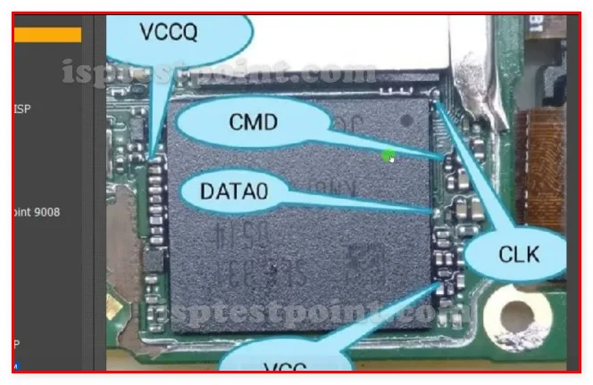
The OPPO A7 CPH1901 uses a Qualcomm Snapdragon 450 platform with an eMMC 5.1 storage chip. The ISP testpoints are located on the back side of the main PCB, typically grouped near the eMMC IC. Technicians must remove the motherboard and inspect under magnification to locate the pads.
- CLK – eMMC clock line
- CMD – Command line
- DAT0 – Data line 0 (minimum required for ISP)
- VCC – eMMC core power supply (2.9 V – 3.3 V)
- VCCQ – eMMC I/O power supply (1.8 V)
- GND – Ground reference
Exact pad coordinates and silkscreen labels are not universally confirmed across all PCB revisions of the CPH1901. Always verify against a high-resolution PCB scan or a trusted board diagram before soldering.
How to Access the Testpoints
Follow this procedure carefully:
- Power off the device completely and disconnect the battery.
- Disassemble the handset and remove the motherboard.
- Identify the eMMC chip and locate the ISP pads under a microscope or magnifier.
- Solder fine gauge (30–32 AWG) wires to CLK, CMD, DAT0, VCC, VCCQ, and GND pads.
- Connect wires to the corresponding ISP socket or adapter on your tool (e.g., EasyJTAG Plus or UMT).
- Launch the software, select the CPH1901 or SDM450 eMMC profile, and supply power.
- Execute your desired operation: read, write, or erase.
Safety Tips Before You Start
Working at chip level carries significant risk. Observe the following precautions:
- Always disconnect the battery before soldering — never work with power applied.
- Use a regulated bench power supply set to correct voltages (VCC 3.3 V, VCCQ 1.8 V); overvoltage will permanently destroy the eMMC.
- Take a full eMMC dump before performing any write or erase operation.
- Use flux and a fine-tip soldering iron at a controlled temperature (320 °C or lower) to avoid pad lift.
- ISP is an irreversible data-loss risk if performed incorrectly — confirm the operation type before executing.
Pin / Test Point Reference
| Pin | Description |
|---|---|
| CLK | eMMC clock signal line — Required for all ISP operations |
| CMD | eMMC command line — Required for all ISP operations |
| DAT0 | eMMC data line 0 — Minimum data line needed for 1-bit ISP mode |
| VCC | eMMC core power supply — 2.9 V – 3.3 V; use regulated supply |
| VCCQ | eMMC I/O interface power supply — 1.8 V nominal |
| GND | Ground reference — Connect to tool ground |
Tools required: EasyJTAG Plus, UMT (Ultimate Multi Tool), Medusa Pro II, UFi Box, RIFF Box 2
Supported operations: Read Firmware (eMMC Dump), Write Firmware, FRP Erase, Dead Boot Repair, Pattern / PIN Lock Remove, User Data Erase
⚠ Safety note: Use correct voltages (VCC 3.3 V, VCCQ 1.8 V). Overvoltage permanently destroys eMMC. Always back up before writing. Disconnect battery before soldering.

Comments (0)
Be the first to comment.