What Is ISP Pinout
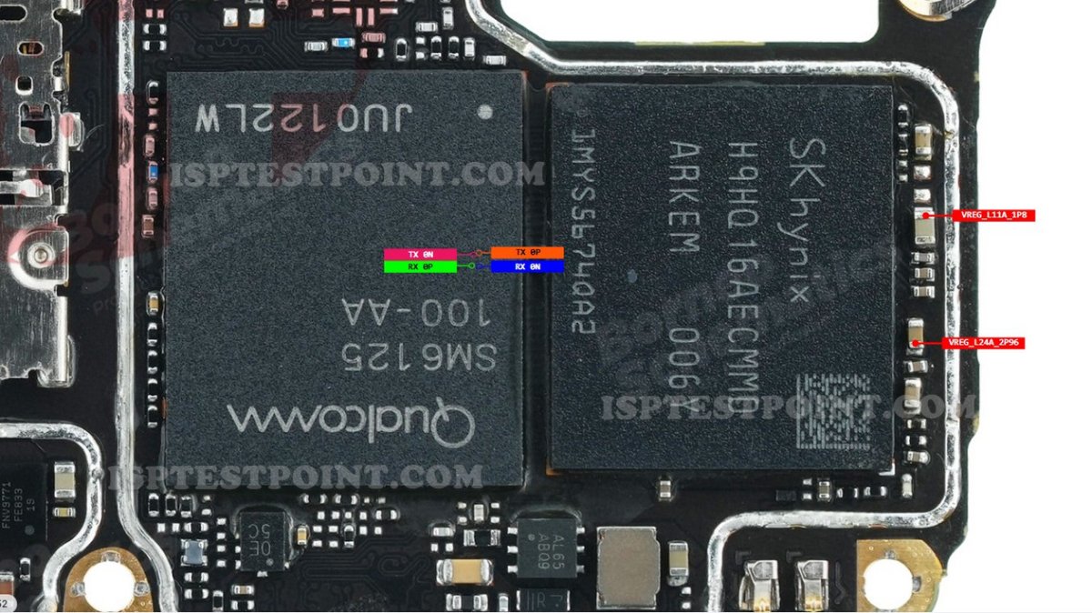
ISP (In-System Programming) pinout is a direct hardware access method that allows technicians to communicate with a device's NAND flash memory chip without relying on the main CPU or bootloader. By identifying and connecting to specific test pads on the PCB that are wired directly to the eMMC, a compatible ISP tool can read, write, or erase flash memory at the hardware level. This technique bypasses all software locks, making it invaluable for scenarios where normal fastboot or EDL-based methods are unavailable or have failed. The OPPO A52 CPH2059 uses an eMMC 5.1 flash storage chip, and its ISP pads expose the standard eMMC bus signals required for this procedure.
When Technicians Use ISP
ISP access on the OPPO A52 CPH2059 is typically required in the following situations:
- Bootloop or soft-brick: The device powers on but cannot complete the boot sequence due to corrupted firmware partitions.
- Dead boot after failed flash: An interrupted OTA update or incorrect flash attempt has rendered the device completely unresponsive.
- FRP (Factory Reset Protection) lock: The device is locked to a Google account and cannot be bypassed through software methods.
- Locked or inaccessible EDL mode: Qualcomm Emergency Download (EDL) mode is restricted or the device does not enumerate correctly via USB.
- Pattern or PIN lock removal: Screen lock credentials need to be cleared at the partition level.
OPPO A52 ISP Pin Locations
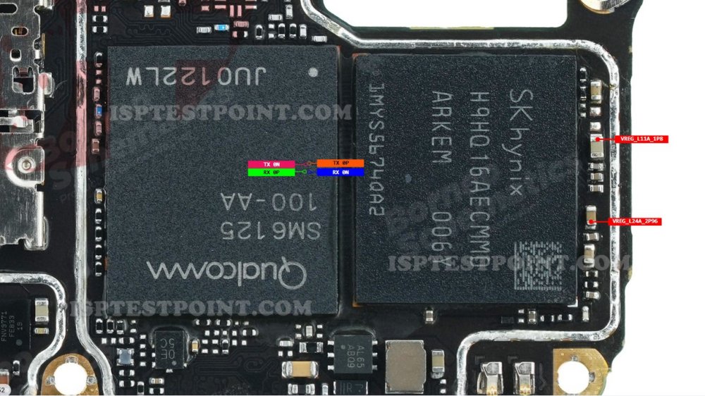
The ISP testpoint pads on the OPPO A52 CPH2059 PCB are located near the eMMC chip on the motherboard. After removing the rear cover, battery, and logic board, inspect the underside of the PCB for the eMMC IC. The standard eMMC ISP signals to locate and connect are listed below. Exact pad coordinates should be verified against a confirmed hardware diagram before connection, as PCB revisions may vary.
- CLK – eMMC clock signal
- CMD – Command line
- DAT0 – Data line 0 (minimum required for ISP mode)
- VCC – eMMC core power supply (typically 3.3 V or 2.9 V)
- VCCQ – eMMC I/O power supply (typically 1.8 V)
- GND – Ground reference
Do not attempt to use DAT1–DAT7 lines unless your ISP tool specifically requires them and you have confirmed pad locations.
ISP Connection Procedure
Follow these steps carefully to perform ISP on the OPPO A52 CPH2059:
- Fully disassemble the device and remove the motherboard. Disconnect the battery.
- Locate the eMMC IC and identify the CLK, CMD, DAT0, VCC, VCCQ, and GND test pads using a verified PCB diagram.
- Solder fine gauge (30–32 AWG) ISP wires to each pad or use a compatible ISP clip/socket if available.
- Connect the wires to your ISP tool's corresponding header pins.
- Open your ISP tool software, select the correct eMMC ISP pinout for the OPPO A52 or CPH2059, and set voltage to match the device specifications.
- Power on the ISP tool (do not connect the device battery). Initiate detection and verify the eMMC is recognized.
- Select your operation: read backup, erase FRP, or write firmware. Complete the process and safely disconnect.
Safety Tips Before You Start
ISP is an advanced hardware procedure. Observe these precautions before proceeding:
- ESD protection: Always work on an anti-static mat and wear a grounded wrist strap.
- Voltage accuracy: Verify VCC and VCCQ voltages before powering on. Incorrect voltage will permanently damage the eMMC.
- Full backup first: Always read and save a full eMMC dump before performing any write or erase operation.
- Tool compatibility: Confirm your ISP tool supports Qualcomm-platform eMMC 5.1 devices and has an updated pinout database.
- Pad condition: Inspect solder joints under magnification. Cold or bridged joints cause read errors and potential data loss.
Pin / Test Point Reference
| Pin | Description |
|---|---|
| CLK | eMMC clock signal pad on CPH2059 PCB — Exact pad location must be verified on hardware; varies by PCB revision |
| CMD | eMMC command line pad — Exact pad location must be verified on hardware |
| DAT0 | eMMC data line 0 — minimum required for ISP communication — Exact pad location must be verified on hardware |
| VCC | eMMC core power supply — typically 2.9 V or 3.3 V — Confirm voltage with multimeter before connecting |
| VCCQ | eMMC I/O power supply — typically 1.8 V — Confirm voltage with multimeter before connecting |
| GND | Ground reference pad — Multiple GND points available on PCB |
Tools required: EasyJTAG Plus, UMT ISP Tool, Medusa Pro II, RIFF Box 2, ATF Box, 30–32 AWG ISP wire or ISP clip
Supported operations: Read Firmware (Full eMMC Dump), Write Firmware, FRP Erase, Dead Boot Repair, Pattern/PIN Lock Removal, IMEI Repair (where legally permitted)
⚠ Safety note: Use correct VCC (2.9–3.3 V) and VCCQ (1.8 V) only. Incorrect voltage permanently damages the eMMC. Always take a full backup before any write operation. ESD precautions mandatory.

Comments (0)
Be the first to comment.