What Is a Test Point
A test point is a designated conductive pad or set of pads on a device's printed circuit board (PCB) that engineers and repair technicians use to access low-level hardware functions. On the OPPO A15 CPH2185, test points allow a technician to communicate directly with the MediaTek Helio P35 chipset, bypassing normal boot sequences. This is essential when standard software methods fail — for example, when the bootloader is locked, the device will not power on, or conventional flashing tools cannot detect the phone. By shorting specific pads, the chipset is forced into Emergency Download (EDL) or BROM (Boot ROM) mode, where repair software can read, write, or erase the eMMC storage directly.

When Technicians Use This Method
Test point access on the OPPO A15 CPH2185 becomes necessary in several common repair scenarios:
- Dead Boot Recovery: The device shows no signs of life after a failed firmware flash or corrupted bootloader.
- FRP (Factory Reset Protection) Bypass: The phone is locked to a Google account and conventional unlocking methods are unavailable.
- Pattern or PIN Lock Removal: Screen lock credentials are unknown and ADB access is disabled.
- Firmware Flashing: The device cannot enter download mode through button combinations alone.
- IMEI Repair: EFS partition damage requires direct eMMC access.
In all these cases, forcing the MediaTek BROM mode via the test point gives repair tools the direct hardware access they require.
OPPO Test Point Download All Models
Locating the Test Point
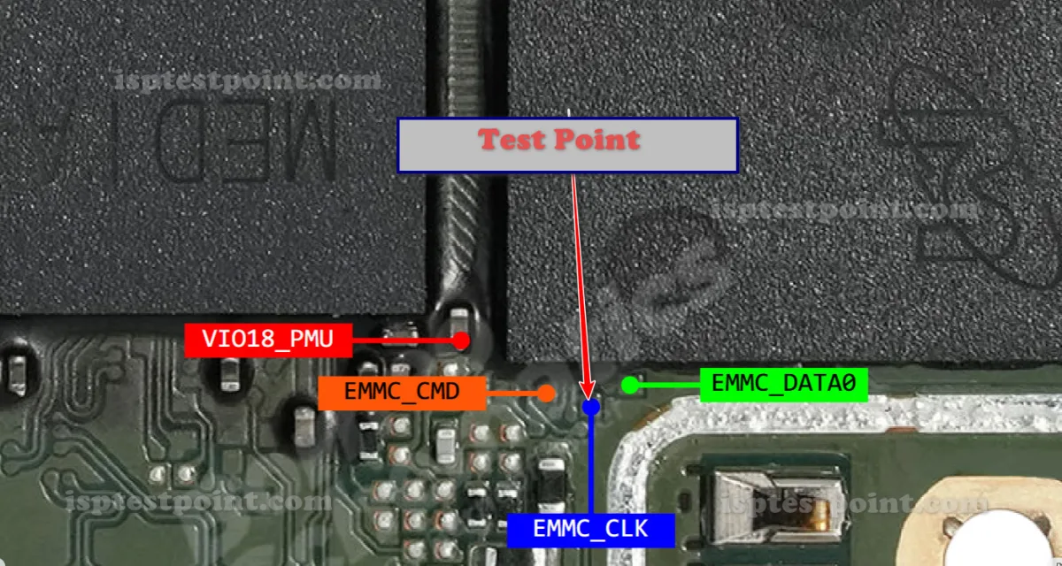
On the OPPO A15 CPH2185, the primary test point pad used to trigger BROM/EDL mode is located on the main PCB, near the MediaTek MT6765 chipset. After removing the back cover and battery, disconnect the display and battery connectors. The relevant test point pad is situated close to the CPU, typically in the upper-central area of the board. It is a small exposed copper pad that must be shorted to the adjacent ground pad. Referencing a high-resolution PCB diagram specific to the CPH2185 revision is strongly recommended before proceeding, as pad positions can vary slightly between board revisions.
Step-by-Step Access Procedure
Follow these steps carefully to enter BROM mode using the test point:
- Power off the device completely and disconnect the battery.
- Remove the back cover and locate the main PCB test point pad near the MT6765 CPU.
- Using a fine-tipped wire, tweezers, or a test point clip, prepare to short the test point pad to the nearest ground point.
- Connect the USB cable to your PC with the repair tool (e.g., SP Flash Tool or UMT) already open and waiting for a device in BROM mode.
- While keeping the test point shorted, reconnect the battery or apply 3.8 V via a power supply, then plug in the USB cable.
- Hold the short for 3–5 seconds. The tool should detect the device in BROM or META mode.
- Release the short and proceed with your flashing or repair operation.
Safety Tips and Precautions
Working at the PCB level carries real risks. Observe the following precautions:
- Always use an anti-static wrist strap and work on an ESD-safe mat.
- Never apply more than 3.8 V to the board; overvoltage will permanently damage the chipset.
- Confirm your firmware file matches the exact CPH2185 model and region before flashing.
- Do not hold the test point short longer than necessary — prolonged shorting can cause heat damage.
- Back up all accessible data before any eMMC-level operation, as these procedures can wipe user data.
- Use quality, well-insulated tools to avoid accidental shorts to nearby components.
Pin / Test Point Reference
| Pin | Description |
|---|---|
| BROM Test Point (TP_CPU) | Small exposed PCB pad near MediaTek MT6765 CPU; short to adjacent GND pad to force BROM/META mode — Exact pad coordinates vary by PCB revision; verify with a CPH2185-specific board diagram |
| GND | Ground reference pad adjacent to the BROM test point; used as the shorting target — Multiple GND points available on PCB shield frame |
Tools required: SP Flash Tool (MediaTek), UMT (Ultimate Multi Tool), Miracle Thunder, EasyJTAG Plus, Fine-tipped tweezers or test point wire, Anti-static wrist strap, USB Type-C cable (data-capable), DC power supply (3.8 V, optional)
Supported operations: Dead Boot Repair, FRP Erase, Firmware Flashing, Pattern/PIN Lock Removal, IMEI Repair, Read Firmware (backup), Format/Factory Reset
⚠ Safety note: Use 3.8 V only. Incorrect shorting or overvoltage can permanently damage the MT6765 chipset. Always verify firmware matches CPH2185 exactly before flashing.

Comments (0)
Be the first to comment.