What Is ISP Pinout
ISP (In-System Programming) is a hardware-level method that allows technicians to communicate directly with a device's eMMC storage chip without removing it from the PCB. By connecting a compatible programmer to specific test pads on the motherboard, the eMMC can be read, written, or erased at the chip level. This technique bypasses the device's operating system entirely, making it invaluable when software-based tools fail. ISP is widely used for FRP (Factory Reset Protection) bypass, pattern lock removal, dead boot recovery, and full firmware flashing when the device cannot boot or respond to standard recovery modes.

OPPO A12 CPH2083 ISP Pinout
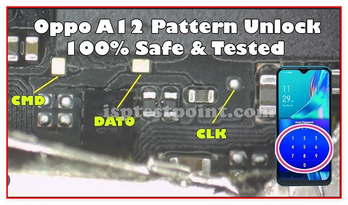
The OPPO A12 CPH2083 is powered by the MediaTek Helio P35 (MT6765) SoC and uses an eMMC 5.1 flash storage interface. The ISP test points are located on the rear side of the motherboard. Technicians must carefully identify the following pads before making any connections:
- CLK – eMMC clock signal pad
- CMD – Command line pad used for read/write instructions
- DAT0 – Primary data line (DAT0 is minimum required for ISP mode)
- VCC – eMMC core power supply (typically 3.3 V)
- VCCQ – eMMC I/O voltage (typically 1.8 V)
- GND – Common ground reference pad
- RST – Reset line pad (required by some programmers)
Exact PCB pad coordinates and silkscreen labels for this specific board revision have not been independently verified in public documentation; technicians should cross-reference a physical board scan or a trusted service schematic before soldering.
When Technicians Use ISP
ISP access becomes necessary in several common repair scenarios. Dead boot situations — where the device powers on but does not progress past a blank screen — often require a direct firmware write via ISP. FRP lock removal after a hard reset without Google account credentials is another frequent use case. Pattern lock or PIN bypass when the device is not enrolled in any MDM also benefits from ISP-level eMMC erasure. Additionally, corrupted bootloader partitions that prevent EDL or fastboot access can typically be recovered through ISP programming.
How to Access ISP Test Points
Begin by powering off the device completely and removing the SIM tray. Use a heat gun or suction cup tool to detach the rear cover, then remove the battery connector and battery. Unscrew all visible Phillips screws securing the motherboard shield and lift the board carefully. Flip the motherboard to expose the rear side where eMMC test pads are located. Clean the target pads with IPA and a fine brush. Solder thin 30 AWG wires to CLK, CMD, DAT0, VCC, VCCQ, GND, and RST pads, then connect these wires to your ISP programmer's corresponding header pins. Open your programmer software, select the MediaTek eMMC or generic eMMC ISP mode, and initiate detection.
Safety Tips and Precautions
Always wear an anti-static wrist strap and work on an ESD-safe mat. Verify your programmer's voltage output before connecting — VCC must not exceed 3.3 V and VCCQ must not exceed 1.8 V for this eMMC standard. Double-check all wire assignments before powering the programmer; reversed VCC or GND lines can permanently damage the eMMC or CPU. Use a bench power supply with current limiting set to 500 mA as an added safeguard. Never connect or disconnect wires while the programmer is powered. Back up the full eMMC dump before making any write operations to allow recovery if something goes wrong.
Pin / Test Point Reference
| Pin | Description |
|---|---|
| CLK | eMMC clock signal test pad — Required for all ISP operations |
| CMD | eMMC command line pad — Carries read/write command data |
| DAT0 | Primary eMMC data line — Minimum data line needed for ISP mode |
| VCC | eMMC core power supply pad — Typically 3.3 V; verify before connecting |
| VCCQ | eMMC I/O voltage pad — Typically 1.8 V on eMMC 5.1 devices |
| GND | Ground reference pad — Multiple GND pads may be available |
| RST | eMMC reset line pad — Required by some programmers; may be optional on others |
Tools required: EasyJTAG Plus, UMT Pro (eMMC ISP mode), Medusa Pro II, RIFF Box 2, 30 AWG ISP wire set, Soldering iron (fine tip), IPA cleaning solution, Anti-static mat and wrist strap
Supported operations: Full eMMC Read/Backup, Firmware Write (Dead Boot Repair), FRP Erase, Pattern/PIN Lock Removal, Bootloader Partition Repair, IMEI Area Backup
⚠ Safety note: VCC max 3.3 V, VCCQ max 1.8 V. Verify all wiring before powering programmer. Incorrect connections may permanently damage eMMC or CPU.

Comments (0)
Be the first to comment.