Overview
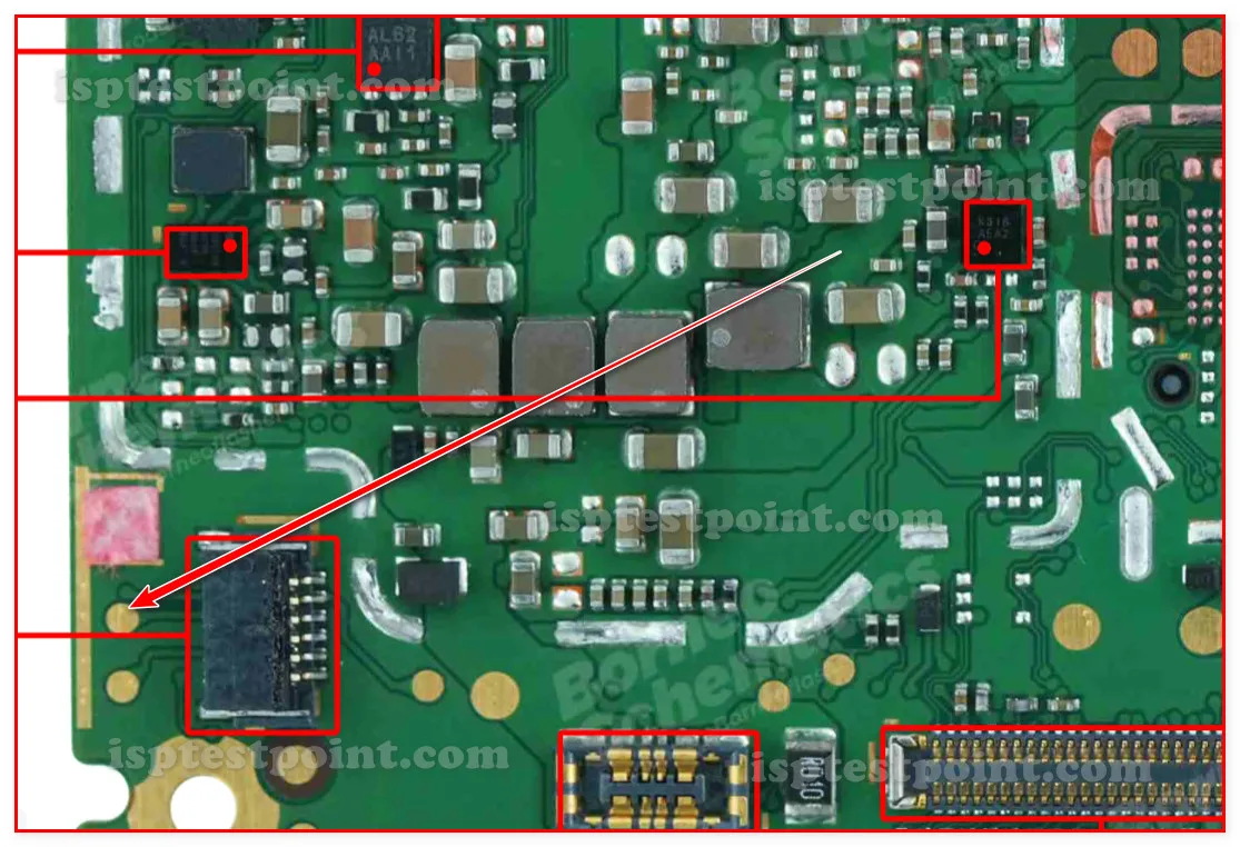
The Huawei Y5 Prime 2018 (DRA-LX2) is a budget-tier Android device requiring direct test point access for advanced diagnostics, firmware recovery, and FRP credential removal. Test points provide technicians with low-level hardware verification when the device fails to boot or exhibits persistent software locks. This reference guide identifies critical measurement and probe locations for efficient troubleshooting without requiring full system boot.

When to Use Test Points
Test point access becomes necessary in the following scenarios:
- Dead Boot / No Power: Device shows no charging indicator or system response despite proper charger connection.
- FRP Lock Bypass: Device requires Google account verification that cannot be bypassed through standard recovery methods.
- Firmware Corruption: OS fails to load after interrupted update or factory reset loop.
- USB Not Detected: Computer does not recognize device in any boot mode; direct eMMC access needed.
- Bootloader Verification: Confirming power delivery to CPU and memory before attempting flash operations.
Key Test Point Locations
The Y5 Prime 2018 DRA-LX2 features test pads located near the charging port and CPU region. Power rail test points include VBAT (battery input), VDDQ (eMMC supply), and multiple GND pads for continuity verification. The device uses a Qualcomm MSM8917 processor paired with onboard storage; eMMC test pads are accessible on the underside of the mainboard near the processor. USB D+ and D− signal lines can be probed at the USB connector assembly for data transmission diagnostics. Critical measurement points allow verification of 3.3V logic levels before attempting ISP operations.
Access Procedure
Safe test point probing requires:
- Power down the device completely and disconnect the battery.
- Remove protective shields and thermal pads obscuring test pad clusters.
- Clean test pads with isopropyl alcohol and allow to dry fully.
- Use a digital multimeter (DMM) set to DC voltage mode for power rail measurement.
- Connect the DMM black probe to GND; touch red probe to each test pad for baseline readings.
- Reconnect battery and measure again to confirm voltage stability under load.
- For eMMC access, use UMT or EasyJTAG Plus ISP cables with appropriate pin headers.
- Verify all connections before applying power to ISP equipment.
Safety Precautions
Excessive probe pressure can lift component pads or short adjacent traces. Use calibrated fine-tip probes rated for 0.5mm pitch or smaller. Never probe while the device is powered without proper equipment grounding. High voltage transients from charger input can damage multimeters; isolate power rails first. Do not attempt eMMC direct write without professional training. Always verify polarity and voltage specifications before probing. Wear anti-static wrist straps when handling the mainboard to prevent ESD damage to sensitive integrated circuits.
Pin / Test Point Reference
| Pin | Description |
|---|---|
| VBAT | Battery positive supply (3.7–4.2V nominal) — Main power input; verify voltage presence during dead-boot diagnosis |
| GND | Ground reference point (0V) — Multiple pads available; use as DMM reference for all measurements |
| VDDQ | eMMC supply rail (1.8V nominal) — Confirm stable voltage before ISP operations |
| USB_D+ | USB data line positive — Signal verification when device not recognized by computer |
| USB_D− | USB data line negative — Signal verification when device not recognized by computer |
| CPU_RST | CPU reset signal — Confirm proper reset pulse during boot diagnostics |
Tools required: Digital Multimeter (DC voltage mode), UMT / UMT_Dongle, EasyJTAG Plus, ISP pin headers and probes (0.5mm pitch), Isopropyl alcohol and fine brush, Anti-static wrist strap
Supported operations: Read Firmware, Write Firmware, FRP Erase, Dead Boot Repair, eMMC Direct Access, Power Rail Verification
⚠ Safety note: Do not probe live circuits without proper grounding. Charger input carries high-voltage transients capable of destroying test equipment. Never short adjacent pads. Device operates at 3.3V logic; use appropriate DMM settings. ISP operations require professional expertise; incorrect procedures may permanently damage the eMMC.

Comments (0)
Be the first to comment.